Aprašymas
Connection.
On the back of the CombiBox there are 2 connectors:
J2534 connector for adapter connection (Scanmatik 2 (PRO))
The connector has the following wiring diagram:
1 — GPT2;
2 — GPT1;
4 — GND;
5 — GND;
6 — CAN-H;
7 — K-LINE;
12 – SELECT BOOT
14 — CAN-L;
15 — L–LINE;
16 — +12V.
DC 12V — connector is designed for power connection.
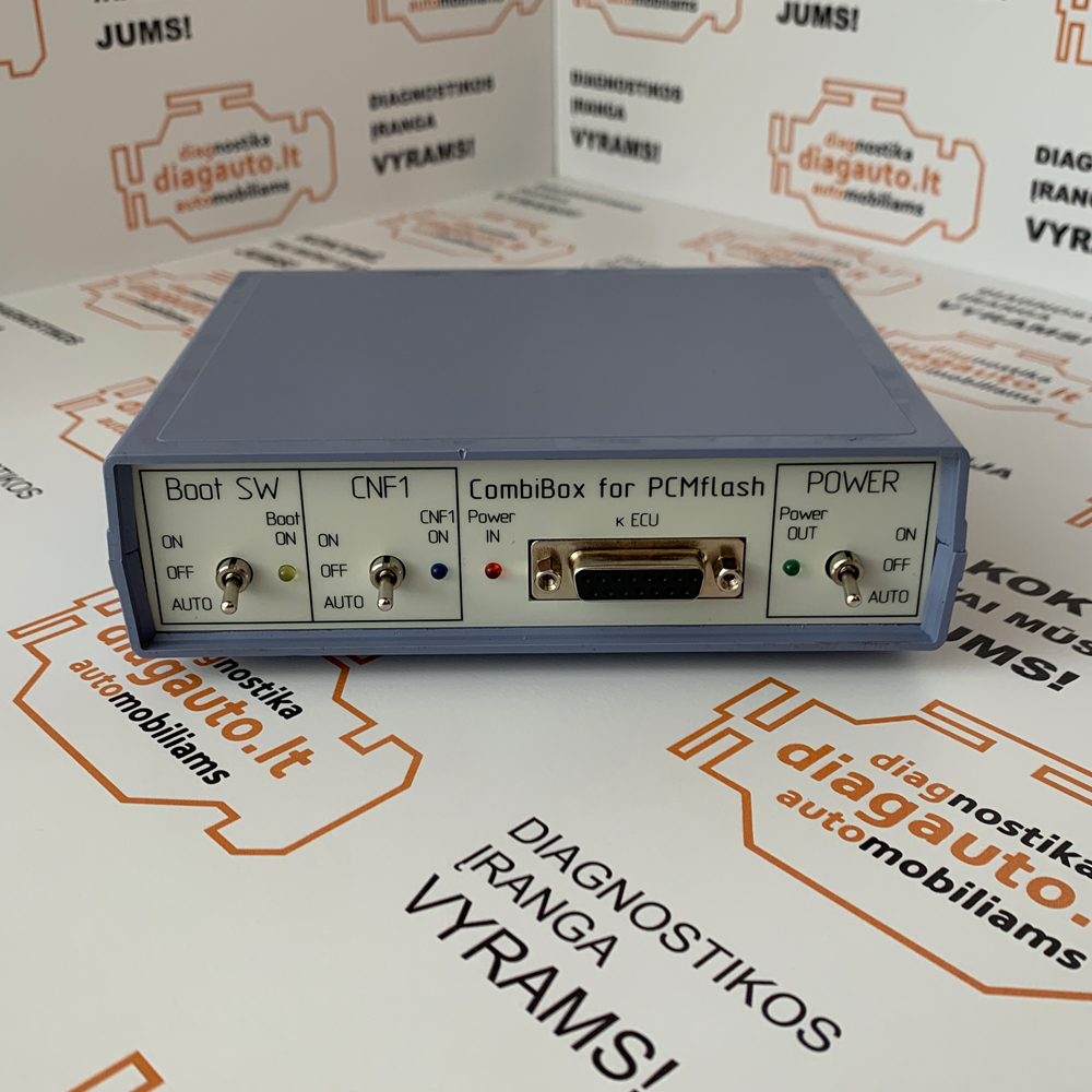
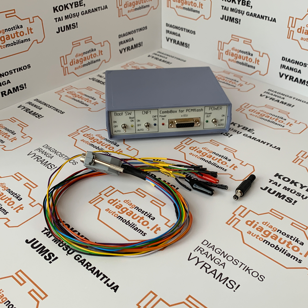
On the front panel of the device there is a connector DB-15, designed to connect to the ECU using a universal cable. All cable lines are appropriately labelled for proper connection.
The connector has the following wiring diagram:
2 — Purple, VPP;
3 — Green-red, GPT2;
4 — Blue, CNF1;
5 — Red, Power +12V;
7 — White, CAN-H;
9 — Orange, Key +12V;
10 — Gray, BOOT;
11 — Black, GND;
12 — Yellow-orange, GPT1;
14 — Yellow, K-Line;
15 — Green, CAN-L.
Controls
The switch is „POWER”, power management. The device has three modes of power supply to the ECU:
„OFF” is off, allows you to remove all power and control signals from the DB-15 connector.
„ON” is on, supplies power to the VECU and VKEY terminals, as well as to the control outputs, depending on the chosen tactics of the BOOT switch.
„AUTO” automatic control, in this mode power management is performed by the PCMflash loader.
„Boot SW” switch, BOOT signal control:
„OFF” is off, allows you to remove all control signals from the DB-15 connector;
„ON” enabled, pulls BOOT to the signal minus;
„AUTO” automatic control, in this mode simultaneous control of signals is produced by the PCMflash loader.
Switch „CNF1”, signal control CNF1 (3.3 volts):
„OFF” is off, allows you to remove all control signals from the DB-15 connector;
„ON” enabled, pulls CNF1 to +3.3 volts;
„AUTO” automatic control, in this mode simultaneous control of signals is produced by the PCMflash loader.
The device has built-in current-limiting resistors on the signal lines:
«BOOT» — 1 kOhm;
«CNF1» — 510 Ohm;
The load on the „CAN” bus is 120 Ohms.
Indicators:
LED indicator „Power IN” indicates the presence of a supply voltage;
LED indicator „Power OUT” indicates the presence of voltage on the ECU;
The LED indicator „Boot ON” indicates the presence of a BOOT signal lift;
The LED indicator „CNF1 ON” indicates the presence of a CNF1 signal lift.